- 您现在的位置:买卖IC网 > Sheet目录1993 > DS1308U-3+ (Maxim Integrated Products)IC RTC 56BYTE NVRAM I2C 8UMAX
DS1308
Low-Current I2C RTC with 56-Byte NV RAM
9
Maxim Integrated
Freshness Seal Mode
When a battery is first attached to the device, the device
does not immediately provide battery-backup power to
the RTC or internal circuitry. After VCC exceeds VPF,
the devices leave the freshness seal mode and provide
battery-backup power whenever VCC subsequently falls
below VBAT. This mode allows attachment of the battery
during product manufacturing, but no battery capacity is
consumed until after the system has been activated for
the first time. As a result, minimum battery energy is used
during storage and shipping.
Oscillator Circuit
The DS1308 uses an external 6pF 32.768kHz crystal. The
oscillator circuit does not require any external resistors or
capacitors to operate. See Table 2 for the external crystal
parameters. The Functional Diagram shows a simplified
schematic of the oscillator circuit. The startup time is
usually less than 1 second when using a crystal with the
specified characteristics.
Whenever VCC > VPF, a 5Fs glitch filter at the output of
the crystal oscillator is enabled.
Clock Accuracy
The accuracy of the clock is dependent upon the
accuracy of the crystal and the accuracy of the match
between the capacitive load of the oscillator circuit and
the capacitive load for which the crystal was trimmed.
Crystal frequency drift caused by temperature shifts
creates additional error. External circuit noise coupled
into the oscillator circuit can result in the clock running
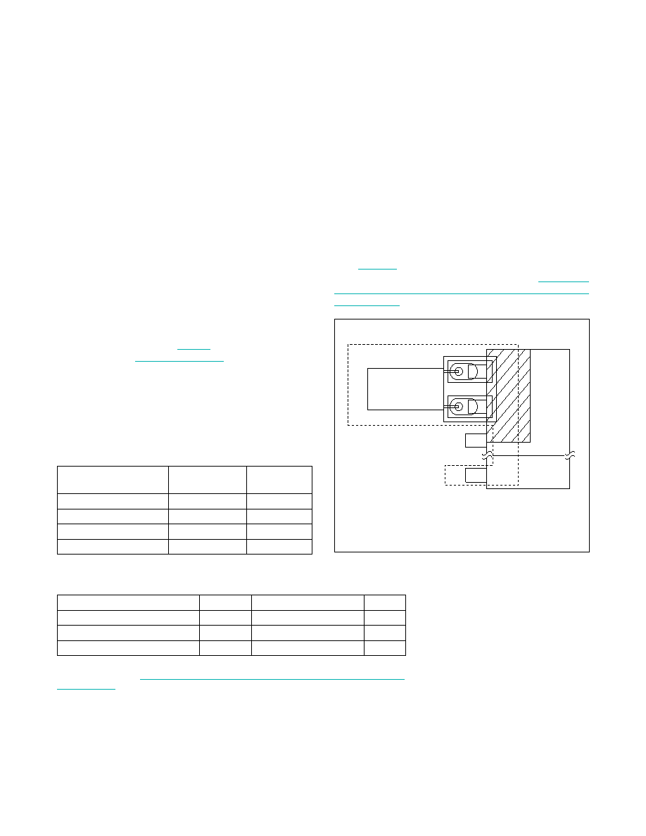
fast. Figure 3 shows a typical PCB layout for isolating
the crystal and oscillator from noise. Refer to Application
Note 58: Crystal Considerations with Maxim Real-Time
Clocks (RTCs) for detailed information.
Table 1. Power Control
Table 2. Crystal Specifications
Note: The crystal, traces, and crystal input pins should be isolated from RF generat-
ing signals. Refer to Application Note 58: Crystal Considerations for Maxim Real-Time
Clocks (RTCs) for additional specifications.
Figure 3. Typical PCB Layout for Crystal
SUPPLY CONDITION
READ/WRITE
ACCESS
POWERED
BY
VCC < VPF, VCC < VBAT
No
VBAT
VCC < VPF, VCC > VBAT
No
VCC
VCC > VPF, VCC < VBAT
Yes
VCC
VCC > VPF, VCC > VBAT
Yes
VCC
PARAMETER
SYMBOL
MIN
TYP
MAX
UNITS
Nominal Frequency
fO
32.768
kHz
Series Resistance
ESR
100
kI
Load Capacitance
CL
6
pF
CRYSTAL
X1
X2
GND
LOCAL GROUND PLANE (LAYER 2)
NOTE: AVOID ROUTING SIGNALS IN THE CROSSHATCHED AREA (UPPER LEFT-HAND
QUADRANT) OF THE PACKAGE UNLESS THERE IS A GROUND PLANE BETWEEN THE
SIGNAL LINE AND THE PACKAGE.
发布紧急采购,3分钟左右您将得到回复。
相关PDF资料
DS1315EN-5/T&R
IC TIME CHIP PHANTOM 20-TSSOP
DS1318E+
IC COUNTER ELAPSED TIME 24-TSSOP
DS1337S+C01
IC RTC SERIAL 2WIRE LP 8-SOIC
DS1338C-33#T&R
IC RTC 56BYTE NV SRAM 16SOIC
DS1339AU+
IC RTC I2C W/ALARM 8USOP
DS1339C-2#
IC RTC I2C W/ALARM 16-SOIC
DS1340Z-33/T&R
IC RTC I2C W/CHARGER 3.3V 8-SOIC
DS1340Z-3
IC RTC I2C W/CHARGER 3V 8-SOIC
相关代理商/技术参数
DS1308U-3+T
功能描述:实时时钟 LOW CUR 3V I2C RTC
RoHS:否 制造商:Microchip Technology 功能:Clock, Calendar. Alarm RTC 总线接口:I2C 日期格式:DW:DM:M:Y 时间格式:HH:MM:SS RTC 存储容量:64 B 电源电压-最大:5.5 V 电源电压-最小:1.8 V 最大工作温度:+ 85 C 最小工作温度: 安装风格:Through Hole 封装 / 箱体:PDIP-8 封装:Tube
DS1308U-33
制造商:MAXIM 制造商全称:Maxim Integrated Products 功能描述:Low-Current I2C RTC with 56-Byte NV RAM
DS1308U-33+
功能描述:实时时钟 LOW CUR 3.3V I2C RTC
RoHS:否 制造商:Microchip Technology 功能:Clock, Calendar. Alarm RTC 总线接口:I2C 日期格式:DW:DM:M:Y 时间格式:HH:MM:SS RTC 存储容量:64 B 电源电压-最大:5.5 V 电源电压-最小:1.8 V 最大工作温度:+ 85 C 最小工作温度: 安装风格:Through Hole 封装 / 箱体:PDIP-8 封装:Tube
DS1308U-33+T
功能描述:实时时钟 LOW CUR 3.3V I2C RTC
RoHS:否 制造商:Microchip Technology 功能:Clock, Calendar. Alarm RTC 总线接口:I2C 日期格式:DW:DM:M:Y 时间格式:HH:MM:SS RTC 存储容量:64 B 电源电压-最大:5.5 V 电源电压-最小:1.8 V 最大工作温度:+ 85 C 最小工作温度: 安装风格:Through Hole 封装 / 箱体:PDIP-8 封装:Tube
DS1310
制造商:未知厂家 制造商全称:未知厂家 功能描述:
DS13-1000
功能描述:固态继电器-PCB安装 HIGH FREQUENCY RELAY
RoHS:否 制造商:Omron Electronics 控制电压范围: 负载电压额定值:40 V 负载电流额定值:120 mA 触点形式:1 Form A (SPST-NO) 输出设备:MOSFET 封装 / 箱体:USOP-4 安装风格:SMD/SMT
DS13-1000S
制造商:TE Connectivity 功能描述:High Performance Solid State Relays
DS13-1001
制造商:MA-COM 制造商全称:M/A-COM Technology Solutions, Inc. 功能描述:DS13 Series High Performance Solid State Relays For Loads Up To 2A@60Vdc